Im Pei National Gallery Plan Drawing
A Design for the East Building

Introduction
The National Gallery of Art's E Building, opened to the public on June 1, 1978. This web characteristic presents drawings by the architect I. G. Pei and his design team, and a representation of the three-dimensional model for the project. Built-in in China in 1917, Pei moved to the United states at eighteen to report compages, and eventually received degrees from the Massachusetts Establish of Technology and Harvard Academy. He opened his own firm in New York City in 1955.
On July 9, 1968, the trustees of the National Gallery selected Pei to pattern a building to provide additional space for the permanent collection and temporary exhibitions, likewise every bit a new eye for enquiry in the history of art. The building was to be constructed on the plot of land directly due east of the West Edifice that Congress had reserved for the museum at its establishment in 1937.
The builder faced several challenges. The new building had to fit an irregularly shaped, trapezoidal site; conform to the monumental scale of the Mall; and harmonize with John Russell Pope'due south classicizing West Building, completed in 1941. During the laborious design process, Pei and a small squad of young architects explored many creative possibilities for the building'southward plan, exterior contour, and roofing of the great atrium. The drawings and models shown in this program illustrate diverse phases in the evolution of the terminal design. They were selected from more 150 design drawings and models for the project that I. G. Pei & Partners gave to the athenaeum of the National Gallery of Art in 1986.
Eastward Edifice, 4th Street façade, Photograph: © Dennis Brack/Black Star
one of 11

Building Design
Concept
In a moment of insight, I. K. Pei solved the trouble of the site'south irregular shape past dividing it into an isosceles triangle and a smaller right triangle. He later recalled, "I sketched a trapezoid on the dorsum of an envelope. I drew a diagonal line across the trapezoid and produced two triangles. That was the beginning."
The early sketch (elevation) shows the sectionalisation of the site into ii triangles. The West Building is represented by the lines to the left of the drawing, with the arrow suggesting its potent east-westward axis.
In the quick report of the urban context for the building (bottom) Pei showed the profile and proportions of the E Building in relationship to the Westward Building and the U. S. Capitol.
(top) I. G. Pei. Early conceptual sketch for building programme, National Gallery of Art East Building, fall 1968. Crayon and graphite on tracing paper
(bottom) I. Chiliad. Pei. Early conceptual sketch for building profile with Capitol, National Gallery of Art E Building, fall 1968. Pen on back of receipt
2 of 11
Exploration
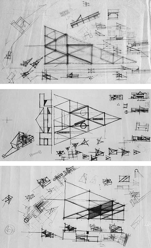
During the fall of 1968 and wintertime of 1969, Pei and his design team explored the underlying geometry governing the structure of the new building. Many of their ideas are recorded in quick working studies, some relating closely to Pei's initial plan based on two triangles and others testing alternative possibilities. Each study may reflect just brief discussion, simply taken together they provide insight into the design process.
The top drawing shows the theoretical point at which the lines formed by the Pennsylvania Avenue and Mall sides of the site would converge, and the human relationship of the building'due south footprint to this larger shape. The pocket-size surrounding drawings explore other geometrical plans and a possible raised skylight structure for the building.
In the middle sketch the architects are studying the interior geometry of the isosceles triangle and considering how to adapt circulation between floors. An culling design for the building's Fourth Street facade and various roof treatments announced in the surrounding drawings.
The lesser pattern explores the possibility of occupying the entire site by adding, at the east terminate, an additional module to Pei's initial conception. The effect emphasizes parallel lines instead of triangles.
(top) I. M. Pei & Partners, National Gallery of Art E Edifice Blueprint Team. Working studies, c. September 1968. Pencil on tracing paper
(eye) I. Chiliad. Pei & Partners, National Gallery of Fine art East Building Blueprint Squad. Working studies, c. October 1968. Felt-tip pen on tracing paper
(bottom) I. M. Pei & Partners, National Gallery of Art East Building Blueprint Team. Working studies, c. October 1968. Crayon on tracing paper
3 of xi
Imaginative Studies
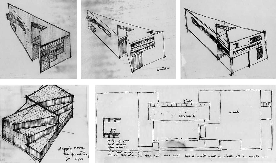
Even before Pei and his team had adamant the final ground plan for the new structure, they were exploring other aspects of the pattern. In quick sketches, they studied a variety of ideas for the building's facades and examined ways to bring lite into the museum to enliven its interior and illuminate works of art.
The design of lively and interesting facades for the Mall and Tertiary Street was an important business concern of the architects. The 3 studies above explore variations on a possible treatment of these facades. The Eastward Edifice is the only structure on the Mall without a public entrance facing in that direction.
The drawing at lower left is for a pattern that would allow light to penetrate the interior of the building through skylights at several levels. The drawing at lower right shows a plan close to the final blueprint of the 4th Street facade, merely with a horizontal ring of windows above the archway. The architects' discussions are reflected in notes on the drawings.
(top) I. One thousand. Pei & Partners, National Gallery of Art Eastward Building Design Team. Studies for Tertiary Street and Mall facades, nos. 1, 2, and iii. Pen (or pen and graphite) on tracing paper
(bottom left) I. M. Pei & Partners, National Gallery of Art East Edifice Design Team. Study, "Stepping down the geometry for light." Pen on tracing paper
(bottom right) I. Chiliad. Pei & Partners, National Gallery of Art East Edifice Design Team. Written report for Fourth Street facade. Pen on tracing paper
4 of 11
Concluding Form
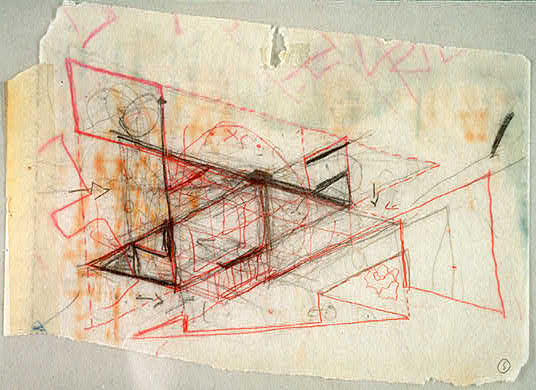
Pei's rare drawings are typically footling more than quick scribbles to communicate his ideas in meetings or conversations. He observed that he would "put ideas in the head and eliminate them in the head....Drawing is not fast plenty, for me anyway."
Early in 1969, Pei's design was refined and elaborated to near-final form. The 2 triangles of the architect's original conception were pulled autonomously to create a slot that would emphasize the separateness of the two spaces: one for the museum's public functions and the other for its study middle. Three towers were kickoff to sally at the corners of the isosceles triangle, balancing the east-west axis of the West Building.
I. M. Pei. Working sketch for building plan, National Gallery of Art East Building, winter 1969. Pen and graphite on tracing newspaper
v of 11
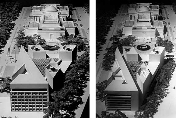
The Calibration Model
This model was made to evidence how the museum would appear after the East Building was completed. In its outset version, shown in the photograph at lower left, the building'south Tertiary Street and Mall facades had deeply recessed windows that created a grillelike pattern. Afterwards, these facades were completely revised. In the concluding version, shown in the model and in the photograph at lower right, the Third Street facade became a sleek plane articulated by assuming horizontal bands of marble. The Mall facade was transformed into a window wall, partially angled back to reflect the building's geometry and broken by a tall window to illuminate the library within.
Pei's original program for the plaza between the Due east and West Buildings included a circular pool, an echo of the one thousand rotunda of the original building. Eventually this programme was replaced by scattered skylights ("crystals") and a waterfall to add light and move to the concourse linking the two buildings underground.
(left) Scale model of East and West Buildings showing early blueprint for Third Street facade, jump 1971
(correct) Calibration model of E and West Buildings showing final design for Third Street facade, spring 1971
6 of 11
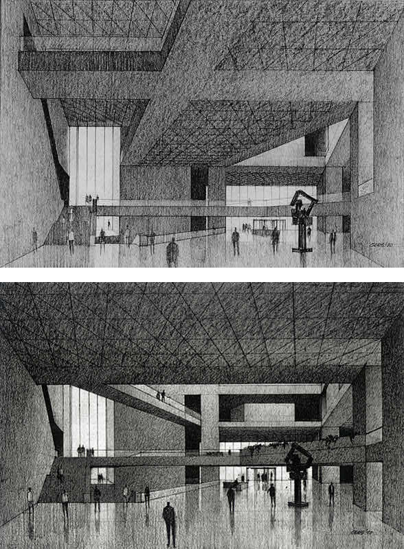
The Atrium
Concrete Coffers
In November 1970, with ground breaking only months away, Pei and his team turned their attending to the vexing question of the roof for the central atrium. To aid the designers envision the appearance of the interior infinite, Pei called on artist/architect Paul Stevenson Oles to make perspective drawings that also depicted the textures of the building materials and the effects of lite in the space.
The first idea for the atrium called for a coffered physical ceiling (the underside of a high upper floor) over the enormous expanse. In drawings Oles fabricated to test this concept, the ceiling seems to overpower the interior, creating what the architects feared would be a "barnlike" temper. This discovery led to a major rethinking of the atrium design.
In the study on elevation, a high upper floor covers much of the atrium.
The drawing on the bottom shows that afterward nearly a month of study the upper level has been cut dorsum to embrace less of the atrium and an aeriform walkway has been introduced to provide circulation at the museum's upper flooring
(superlative) Paul Stevenson Oles. Perspective study for garden courtroom, National Gallery of Art East Building, 6 November 1970. Graphite on paper
(bottom) Paul Stevenson Oles. Perspective written report for garden courtroom, National Gallery of Art East Building, 1 December 1970. Graphite on paper
vii of 11
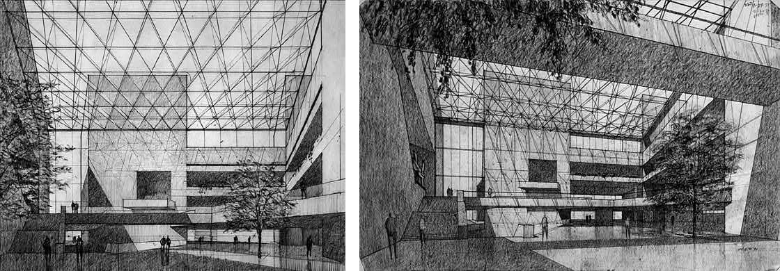
Skylights
By Jan of 1971, Pei had agreed that instead of a concrete ceiling a skylight system should be designed, which would open the atrium to natural lite. The tops of the towers at the 3 corners of the triangular atrium would be visible through the glass to help orient visitors.
In the left cartoon the effect of the high skylight system in the atrium can be seen, dwarfing copse, visitors, and potentially works of art.
The correct drawing was prepared inside a week of the ane on the left. It introduces a concrete bridge, seen in the upper foreground, to aid bring man scale to the enormous space. The architects still were dissatisfied with the outcome.
The concept of an open interior court was an important breakthrough, yet Oles' drawings over again revealed problems in the pattern. The drawings showed that the loftier skylights with their small panes of glass would be out of proportion to the grand atrium space. The architects also feared that the many minor metal pieces of the skylight frame would read every bit a heavy fiber, distracting attention from the essential geometry of the space.
(left) Paul Stevenson Oles. Perspective report for skylight system, National Gallery of Art East Edifice, 25 January 1971. Graphite on paper
(right) Paul Stevenson Oles. Perspective report for skylight system with span, National Gallery of Fine art E Edifice, 1 February 1971. Graphite on paper
8 of eleven
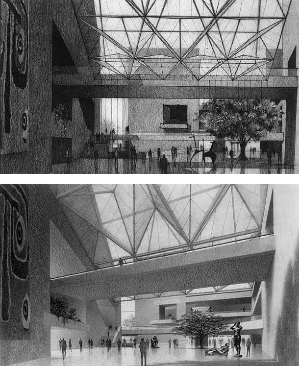
Infinite Frame
In the end, the architects turned to the building's triangular geometry for their solution: a sculptural structure composed of steel-framed modules. The base of each module forms an isosceles triangle, the sides of which have the same 2:3 ratio found in the building.
The meridian cartoon was the first workable plan for the infinite-frame system, the steel and glass structure spanning the atrium. The space frame is composed of larger three-dimensional modules resting at a lower level than the skylights.
In the final pattern for the space frame, tubular aluminum bars were placed confronting the drinking glass panels to reduce glare in the atrium without diminishing the play of light in the space. The atrium every bit built appears remarkably similar to the rendering on the bottom, completed in June 1971.
(top) Paul Stevenson Oles. Perspective study for space frame, National Gallery of Art Eastward Building, i March 1971. Graphite on paper
(lesser) Paul Stevenson Oles. Perspective study for infinite frame with low-cal diffusion confined, National Gallery of Fine art Due east Building, June 1971. Graphite on paper
9 of 11

Technology
The report on the left shows a design for one of the nodes that supports the space frame and locks the beams into place. As built, each of the space-frame tetrahedrons measures 30 feet by 45 feet. The proportions of the entire span of the atrium are in the same ii:3 ratio: 225 feet on 2 sides by 150 feet on the other.
When the architects conceived the atrium space frame spanning 16,000 square feet, no similar structure had been successfully built on such a scale. The framework consists of enormous 5-ton nodes of cast steel welded in identify to beams of rolled steel at very high temperature. Craftsmen contributed enormously to the project'due south success, ultimately earning twenty-three awards for their work.
(left) I. M. Pei & Partners, National Gallery of Art East Building Design Squad. Study for space-frame node, 15 March 1971. Pen on tracing paper
(correct) Unfinished space frame from above, 25 July 1977. Photograph by Stewart Brothers
10 of 11
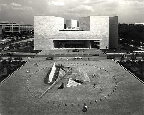
East Edifice of the National Gallery of Fine art shortly afterwards it opened in June 1978. The space-frame structure is visible to a higher place the chief archway.
Photo by Dennis Brack/Black Star
eleven of 11
Source: https://www.nga.gov/features/slideshows/a-design-for-the-east-building.html
0 Response to "Im Pei National Gallery Plan Drawing"
Post a Comment